Slice 1 - Image 1 Slice 1 - Image 2 Slice 1 - Image 3 Slice 1 - Image 4
Slice 2 - Image 1 Slice 2 - Image 2 Slice 2 - Image 3 Slice 2 - Image 4
Slice 3 - Image 1 Slice 3 - Image 2 Slice 3 - Image 3 Slice 3 - Image 4
Slice 4 - Image 1 Slice 4 - Image 2 Slice 4 - Image 3 Slice 4 - Image 4

Experiment Analysis Software

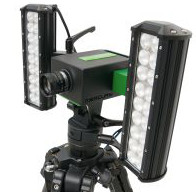
Mercury RT® Industry
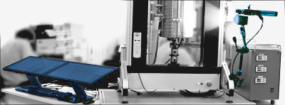
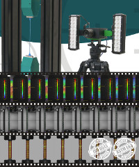
View leaflet

Deformation measurement of samples during material testing with use of the Video extensometer Mercury RT® allows applying multiple virtual probes (Movement Sensors) on markers and advanced image features to be tracked, including the natural pattern of the sample surfaces.
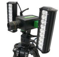
Mercury RT® R&D

View leaflet

The Mercury RT® system enables the user to analyze the measurement either in offline or online modes, thus high-speed cameras can be used. The computation is performed in real-time, where the computed values are transferred to a connected test rig, either via analog or digital outputs.

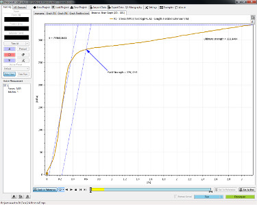
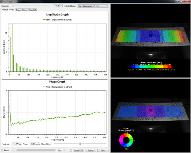
Typical use is the determination of various material properties (tensile tests, uni/biaxial properties, contractions), measurement of large strain rates, high-speed testing, vibration measurement, crack propagation, dynamic testing and quality control.

Measurement Technology

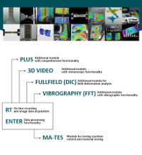
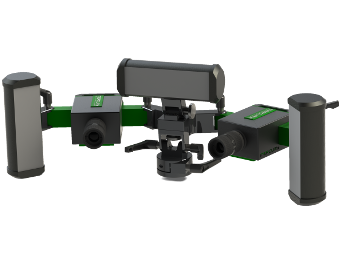
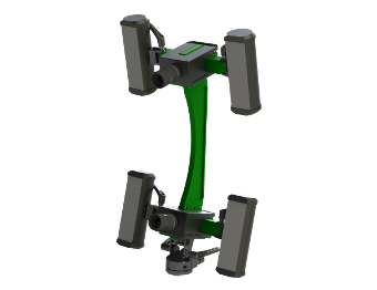
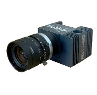
Mercury RT® Modularity
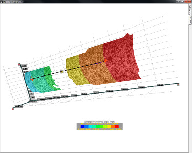
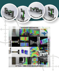
View leaflet

A non-contact optical measurement technology has made a major step in terms of speed and accuracy in recent years. The Mercury RT® measurement system shows in practice following benefits - it measures general deformations (strains and displacements) and any distance change between two markers set in any axis with high sub-pixel accuracy. The Mercury RT® is based on digital image correlation technology (DIC).

The common resolution of standard system is within 500 nm and 5 µm. The system fulfils class 0.5 or B-1 of classification according to ISO 9513 and ASTM E83. In certain camera use case, the system resolution reaches the level of 100 nm - 500 nm and system fulfils the class 0.2. The strain resolution can reach 10 microstrains.

HARDWARE

SINGLE camera system

Specifications:

  • Typical frequency: By model
  • LED light source: 2x 36 W
  • Professional head tripod/frame mounting
  • Direct connection to PC via Ethernet
  • Calibration grids for setting of:
    • Coordinate system
    • Perspective compensation
    • Geometric lens distortions
  • FOV (Field Of View): By model
 

Single camera packaging contains:

  • BFLY single camera videoextensometer
  • 1x lens 25 mm (typical)
  • 2x LED light (2x 36 W)
  • Power adapter
  • Professional head tripod/frame mounting (mounting on test machine handle by using 2x M6 or 1x 3/8 in)
  • Camera to PC cable
  • Dustproof case
  • SW installation USB card
  • Manual

DUAL/MULTIPLE camera system

  • 1x stitching spacer
    (sizes: 70, 100, 140, 200, 300, 400mm, other upon recquest)
  • 2x stitching adapter
Stitching image 
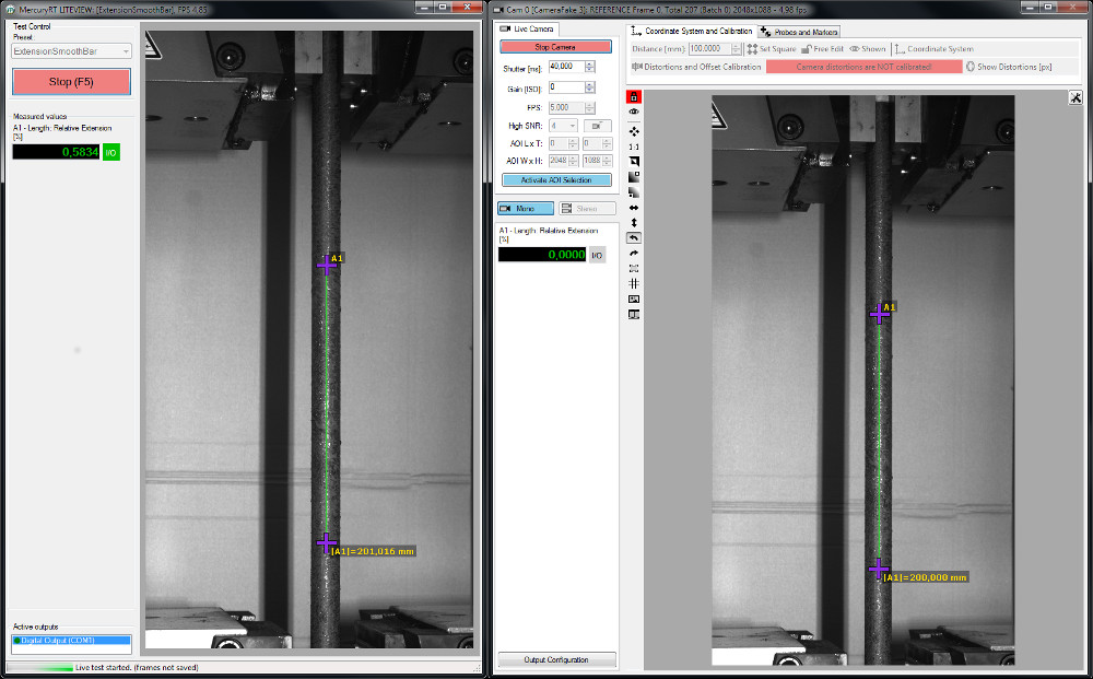
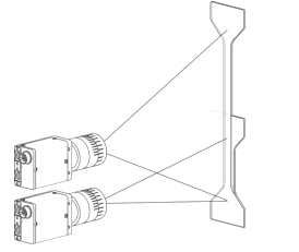
Stitching - Partial overlap image
Stitching image 
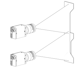
Stitching - Full overlap image

3D horizontal package with adjustable stereo angle

Professional head tripod/frame mounting, sizes 300, 500 mm, other upon request (replacement of two separate BFLY mounts)
  • Stereosystem large dustproof case (replacement of two BFLY cases)
  • 3x LED light source 54 W (replacement of 4x 36 W LED)
  • 3D system power adapter (replacement of 2x BFLY power adapter)
  • 3D synchronization cable

3D vertical package with fixed stereo angle

  • 1x stereo spacer (sizes 350 mm, other upon request)
  • 2x stitching adapter
  • 3D synchronization cable

Custom camera system mounting for various cameras

  • Single, Multiple camera systems
  • Stereo camera systems
  • Integrated or separated illumination

MCR universal cameras with cooler

MCR camera system

MCR050, MCR100, MCR125, MCR150, MCR200, MCR250

High resolution cameras

MCR camera system

MCR300 ~ 16MPx, MCR400 ~ 29MPx

Speed cameras

MCR camera system

  • Camera link, USB 3.0
  • Cameras with real time
  • Recording up to 10,000 fps

High speed cameras

MCR camera system

500-500,000 fps with internal memory

Special cameras

MCR camera system

MCR030 ~ up to 4kHz real time

Syncbox SC-07

Electronic unit for controlling vibration tests, fatigue tests and vibrographic measurements

SYNCBOX is a universal synchronization unit for controlled triggering dynamical, periodical or vibrating process with optical vibrographic system. The unit enables to synchronize up to four independent outputs with connected devices. Synchronized device is triggered by generated voltage pulse. SYNCBOX allows to generate signal with adjustable amplitude and frequency for optional frequency sweep. This feature is especially suitable for control an amplifier or a similar block for driving dynamical test machine, shaker etc. Information about parameters of captured and/or generated signals are sent via USB, Bluetooth using the API.

Typical configurations

1. Trigger box for multi-camera settings synchronization

  • Basic connection – synchronizing on rising edge input TTL pulse
  • Optical system / cameras can be connected together in MASTER / SLAVE mode, triggers can control lights for flashes (e.g. in stereo mode – left / right flash)

2. Synchronization functionalities - Dynamic event triggering

  • Generates trigger pulses on rising edge TTL input signal
  • Adjustable delay and pulse width
  • Trigger on every n-th input TLL pulse
  • Triggering on threshold voltage of input analog signal, same delay for all outputs
  • Adjustable sampling frequency (up to 5 kHz) and number of samples (max. 3000 samples)
  • Captured voltage level for each sampled value
  • Specified number of samples or infinite loop mode

3. Periodic event triggering

  • Triggering on voltage level, minimum, maximum, skip n pulses
  • Frequency detection – mHz resolution
  • Defined maximal number of pulses per second for outputs (FPS)
  • Adjustable phase delay from detected threshold
  • Typical use for fatigue tests

4. Videostroboscope-Vibrograph functionality

  • One trigger per period, triggers are shifted with ϕ (e.g. 5 periods for ϕ = 90°)
  • Minimal ϕ = 0,1° 3600 samples per period
  • Capturing fast periodic signals with sufficient number of periods
  • Easy setup to oversampling

5. Generator functionalities with triggering and accelerometer feedback functionalities

  • Integrated sine wave generator
  • Adjustable signal amplitude and frequency
  • Constant frequency or liner sweep
  • AMPLITUDE / FREQUENCY profile
  • Up to 10 profile points {amplitude, frequency}
  • Linear profile intervals
  • Feedback from sensor – profile could be set in physical measured units (g / frequency profile for accelerometer)

Accessories

  • computer
  • POE LAN card
  • CAN bus device
  • AD/DA device
  • test rig ECU
  • wireless sensors
  • IRC-CUT filters
  • touch screen display
  • laser collimator
  • additional camera
  • sync.box
  • camera tripod
  • calibration grids
  • camera mounting set
  • LED or halogen light sources
  • magic arm
  • transportation box
  • additional lenses

7.8 / 1 000 000 of FOV
  • 0.16 µm @ 20 mm FOV
  • 0.78 µm @ 100 mm FOV
  • 7.81 µm @ 1 m FOV

5.2 / 1 000 000 of FOV
  • 0.10 µm @ 20 mm FOV
  • 0.52 µm @ 100 mm FOV
  • 5.21 µm @ 1 m FOV

4.9 / 1 000 000 of FOV
  • 0.10 µm @ 20 mm FOV
  • 0.49 µm @ 100 mm FOV
  • 4.88 µm @ 1 m FOV

3.6 / 1 000 000 of FOV
  • 0.07 µm @ 20 mm FOV
  • 0.36 µm @ 100 mm FOV
  • 3.63 µm @ 1 m FOV
15.6 / 1 000 000 of FOV
  • 0.31 µm @ 20 mm FOV
  • 1.56 µm @ 100 mm FOV
  • 15.63 µm @ 1 m FOV
7.8 / 1 000 000 of FOV
  • 0.16 µm @ 20 mm FOV
  • 0.78 µm @ 100 mm FOV
  • 7.81 µm @ 1 m FOV
5.2 / 1 000 000 of FOV
  • 0.10 µm @ 20 mm FOV
  • 0.52 µm @ 100 mm FOV
  • 5.21 µm @ 1 m FOV
4.9 / 1 000 000 of FOV
  • 0.10 µm @ 20 mm FOV
  • 0.49 µm @ 100 mm FOV
  • 4.88 µm @ 1 m FOV
3.6 / 1 000 000 of FOV
  • 0.07 µm @ 20 mm FOV
  • 0.36 µm @ 100 mm FOV
  • 3.63 µm @ 1 m FOV
3.0 / 1 000 000 of FOV
  • 0.06 µm @ 20 mm FOV
  • 0.30 µm @ 100 mm FOV
  • 2.96 µm @ 1 m FOV
2.4 / 1 000 000 of FOV
  • 0.05 µm @ 20 mm FOV
  • 0.24 µm @ 100 mm FOV
  • 2.36 µm @ 1 m FOV
2.0 / 1 000 000 of FOV
  • 0.04 µm @ 20 mm FOV
  • 0.20 µm @ 100 mm FOV
  • 2.04 µm @ 1 m FOV
1.5 / 1 000 000 of FOV
  • 0.03 µm @ 20 mm FOV
  • 0.15 µm @ 100 mm FOV
  • 1.52 µm @ 1 m FOV

Tech. specification

Parameters Range * Typical system
Classification to ISO 9513 Class 0.2, 0.5, 1, 2, - Class 1
Classification to ASTM E 83 Class A, B-1, B-2, C, D, E, - Class B-1
Field of View (FOV) 2-2000** mm 60 mm
Gauge Range 0.01-800 % 0.01-10 %
Resolution 0.1-50** μm 1 μm
Analog output 10-16 bit 4V/14 bit
Digital output RS232/422/485, TCP/IP TCP/IP
Test rig connectivity DOLI DoPE, custom DOLI DoPE
Camera resolution 0.3-29 MPx 1.2 MPx
Data rate 0.1-10 000 Hz 50 Hz

* Range depending on the configuration
** Could be increased by different optical system

SOFTWARE

RT

On-line recording and image data acquisition

ENTER

Data processing functionality

PLUS

Additional module with comprehensive functionality

3D VIDEO EXTENSOMETER

Additional module with stereoscopic functionality

TEST RIG

Module for test machine control

FULLFIELD (DIC)

Additional module for field deformation analysis

VIBROGRAPHY (FFT)

Additional module with vibrographic functionality

RT

On-line recording and image data acquisition

  • Recording of various cameras, support of AVT / Prosilica / Teledyne / Videology / Webcam / Cameralink / Basler / PoinGray / Matrix Vision
  • Recorded data browsing (various cameras in parallel)
  • External synchronization and snap mode
  • DSLR camera support (PTP protocol)
  • ROI/AOI (High FPS at lower resolution)
  • Focus and Targeting tool
  • Output to analogue, RS232 and TCP/IP
  • API functions for remote control through RS232 and TCP/IP
  • 2x Point probe online computation
  • 1x Extension line online computation
  • Markers detection
  • Width detection and measurements
  • Automatic coordinate system definition based on grids
  • Coordinate system definition based on reference length
  • Frozen extension line endpoint function
  • Image viewing functions (invert, zoom, over/under exposed indication, flip, rotate)
  • Engineering stress – Engineering strain evaluation
  • True stress - true strain evaluation
  • Extensometer Calibration
  • LiteView graphical user interface for operators
PDF Modularity

ENTER

Data processing functionality

  • Offline computations
  • Multicamera support ( RT + ENTER)
  • Image and video data import
  • Interactive data browsing
  • Data categorization and averaging functions (batching), measurement management (pre-sets / bookmarks)
  • Unlimited virtual measurement tools:
    • Extension line
    • Point probe
    • Strain gauge
  • Coordinate system definition based on reference length
  • Custom expression editor
  • Automatic coordinate system definition based on recorded grids
  • Markers detection
  • Width detection and measurement
  • Frozen extension line endpoint function
  • Image viewing functions (invert, zoom, over/under exposed indication, flip, rotate)
  • Real time data filtering
PDF Modularity

PLUS

Additional module with comprehensive functionality

require ENTER or RT module
  • Multicamera support (RT + PLUS)
  • High speed camera support (RT + PLUS)
  • Stitching mode (extension of field of view by using multiple cameras)
  • Unlimited virtual measurement tools
  • Neck gauge
  • Force gauge
  • Chain probe
  • PIV Field (Particle Image Velocity)
  • Advanced coordinate system set-up based on CAD
  • or CSV data, free-edit function
  • Correction of camera lens distortion
  • QR code sample indexing
  • Coordinate system offset
  • Rigid body motion functionalities
PDF Modularity

3D VIDEO EXTENSOMETER

Additional module with stereoscopic functionality

require ENTER or RT module
  • The stereoscopic DIC (Digital image correlation) functionality
  • Multiple camera pair support
  • 3D camera pairing and adjustment
  • 3D virtual measurement tools:
    • Point probe
    • Line probe
    • Surface strain gauge with texture mapping
  • Advanced coordination system definition in 3D
  • Rigid body motion removal in 3D
  • 3D/2D viewing function
  • CAD data import
  • Geometry export
  • FEM data import
  • CAD/FEM data comparison tool
PDF Modularity

TEST RIG

Module for test machine control

require ENTER module
  • Full DOLI / Custom communication protocol
  • Measurement mode pre-sets (Uniaxial, Bending, Custom, …)
  • Test machine control panel
  • Test rig analogue / digital inputs
  • Young's modulus, Poisson's ratio
  • Ultimate tensile strength, Yield strength
  • Any other calculable material parameters based on measured data
PDF Modularity

FULLFIELD (DIC)

Additional module for field deformation analysis

2D require ENTER module, 3D require ENTER + 3D VIDEO modules
  • Full field analysis based on DIC for speckle pattern and natural pattern
  • Area selection tools for deformation analysis
  • Advanced multi area contour plots for complex analyses
  • Displacement field and strain field calculations
  • Accelerations and velocities
  • FLC curve identification and FLD plot
  • Non uniform field measurements
PDF Modularity

VIBROGRAPHY (FFT)

Additional module with vibrographic functionality

2D require ENTER + FULLFIELD modules, 3D require ENTER + FULLFIELD + 3D VIDEO
  • Spectral and Octave analysis
  • Video stroboscopic functionality (with Sync box)
  • Data signal processing – windowing
  • 2D/3D operational deflection shape (ODS) analysis
  • Signal characteristics (Power spectral density calculation, …)
  • Subset sweep analysis
  • Zero phase point selection
  • Amplitude and Phase plots
  • Campbell diagram plot
PDF Modularity

Features

  • Multiple virtual extensometers per camera input
  • Modular concept beginning by simple camera recorder up to multicamera 3D fullfield system with shaker
  • Wide scope of engineering use:
    • Material testing
    • FEA validation
    • Component testing
    • Vibrography
  • Multi-threaded parallel computation for optimal measurement speed
  • Enhanced graphical user Interface with intuitive controls. Highly efficient video display using OpenGL acceleration
  • Simple system calibration including arbitrarily moveable coordinate system.
  • The system can also be used on natural, non-prepared surfaces (such as wood, fabric, material structure and roughness,...)
  • Customizable export formats
  • Connectivity to a large number of test rigs types
  • System allows to operate with DOLI based equipments
  • Simultaneous data recording and computing
  • Videostroboscopic functionality (synchronization with periodic phenomena)

GUI

Mercury RT® Single-Click LITEView

Mercury RT® GUI Full Mode

Main mercury window with charts and system features

Printscreen

Main mercury window with 3D chart

Printscreen

Main vibrography window
 

Printscreen

Recommended PC configuration

    CPU: scored at least 6000 points according to: www.cpubenchmark.net
    RAM: DDR3 8GB 1333MHz (better to use 16GB)
    HDD: 1TB SATA, 7200rpm, 64MB cache + 80GB SSD
    Graphics: 1GB GDDR3 PCIe x16 NVIDIA
    LAN: Gigabit ethernet PCIe card INTEL
    FireWire: FireWire PCIe IEEE-1394b
    USB: USB 3.0 SuperSpeed PCI-E card adaper
Accessories

APPLICATIONS

TEST RIG
SETTING

test rig setting scheme

VIBROGRAPHY SETTING

vibrography setting scheme

TEST CENTER SETTING

test center setting scheme
Output: Material parameters identification
Output: Modal shapes analysis
Output: ODS (Operating Deflection Shapes) visualization

DOWNLOADS

DEVELOPMENT CENTER

Our company

Sobriety s.r.o. has been serving the industry since 2002 and it has achieved a remarkably successful track record. So far, the company has realized hundreds of projects representing hundreds of thousands hours of human work. The main activities of the company are product development and engineering consulting covering a broad technical field and also in the SW / HW development.

At Sobriety s.r.o., contracts are solved by a large team of internal experts in different fields of technical science and production. Through our services and activities we support product development during its whole life-cycle. The company is a member of Czech Space Alliance and Czech Association of Microturbines and handle several development projects focused on:

  • Underhood thermal management
  • Air intake systems including dust and water management,
  • Turbine and compressor aerodynamics development,
  • Heat exchanger with heat pipe technology development including regulation valves,
  • Air bearing and air sealing development and production,
  • Analog electronics and digital embedded control systems development and production,
  • Engineering and measurement / analysis software development,
  • Special measurement devices development,
  • Optical measurement systems development.

Besides the optical measurement system Mercury RT®, the company's main products are:

  • Special aerodynamic bearing and sealing for the speed ranges from 100 up to 750 ,000 rpm,
  • Bearing and rotor dynamics design software DYNROT,
  • Potential drop technique material measurement systems ACPD / DCPD / corrected DCPD,
  • Aerodynamics SW development tools AEROFLOW .

The Mercury RT® program

The Mercury RT® product is the result of an in-house research and development in the Czech company Sobriety s.r.o. It is widely used in mechanical research, material testing industry and quality control. It includes various software modules and hardware devices. Team of expert engineers provides state of the art development, continuous improvement and customer support.

With Mercury RT® software and devices can anyone provide quick 3D/2D shape and deformation measurement, analyse strains, identify mechanical parameters and measure vibrations, Operation Deflection Shapes and modal shapes and many other. The Mercury RT® technology can simply upgrade any testing machine and provide their retrofits it can also be used as prime control system for any electric driven testing.


Our partners

logo
logo
logo
logo
logo
logo
logo
logo
logo
logo
logo
logo

CONTACT

DEVELOPMENT CENTER

Sobriety s.r.o.
Blanenská 1288/27
664 34 Kuřim
Czech Republic
49°31‘18.28“, 16°53‘66.62“
SALES
+420 541 231 698
SUPPORT
+420 734 393 553
 

DISTRIBUTION

Sobriety s.r.o.
Kuřim
Czech Republic
+420 541 231 698
sales@sobriety.cz
www.sobriety.cz

LABORTECH s.r.o.
Opava
Czech Republic
+420 731 656 723
urban@labortech.cz
www.labortech.cz

Pcb Technologies sas
Viale Beniamino Gigli, 15
60044 Fabriano (AN) - I
Italy
+39.0732.250458
info@pcbtech.it
www.pcbtech.it
 

WANZEL Handels und Projektmanagement Ges.m.b.H.
Wagramer Straße 173/D
A-1220 Wien
Austria
+43 1 259 36 16
wanzel@wanzel.com
www.wanzel.com

Fuchs AG
Markus Fuchs
Empützistrasse 4
8215 Hallau
+41 52 681 37 27
m.fuchs@fuchsag.ch
www.fuchsag.ch
 

DWE Scientific Limited
Unit 5, Falcon Way
Brackley
Northamptonshire
NN13 6PZ
+44 (0)1280 469347
info@dwescientific.com
www.dwescientific.com

Industrial Association "MEGA"
Proyezd Serebryakova d.2,
korpus 1, ofis 812
Moscow
Russia, 129343
+7 (495) 600 36 42
info@pamega.ru
www.pamega.ru

Bestech Australia Pty Ltd.
U14, 44 Garden Boulevard
Dingley, VIC 3172
Australia
+61 03 9540 5100
awieringa@bestech.com.au
www.bestech.com.au
 

Jinan Testing Equipment IE Corporation
Floor 10th Tower A Century Fortune Plaza High Tech.
Zone Jinan 250101
China
+86 531 8651 0535
sales@testingequipmentie.com
www.testingequipmentie.com

Test & Measurement Science
56-4, Deajong-ro
Jung-gu, Deajeon
35040, Republic of Korea
+82 (0)70 8650 0261
tms_info@naver.com
www.tmsci.co.kr


Shanghai Chaokun Testing Equipment Co., Ltd
Room 324, Suite C, 1st Building, No.128
Xiangyin Road, USST National Science Park, Shanghai
200433, P.R.C.
+86 21 6136 2113
huazhiping@chaokun.net

THE UNIVERSAL GRIP COMPANY
72 Loring Avenue, Suite 2
Salem, MA 01970
USA
978-882-1480
ChrisThomas@universalgripco.com
Frank@universalgripco.com
www.universalgripco.com
 

Folio Instruments
277 Manitou Drive Unit A
Kitchener, Ontario
N2C 1L4
Canada
519-748-4612
nhoward@folioinstruments.com
www.folioinstruments.com